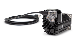


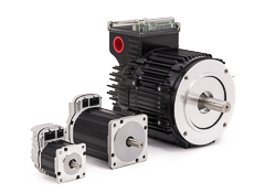


ClearPath All-In-One Servos
ClearPath Overview
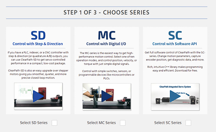
Choose Series
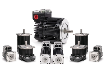
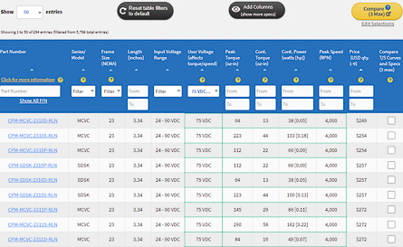
Motor Selection Guide
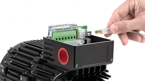
Accessories Guide
Motor Specs
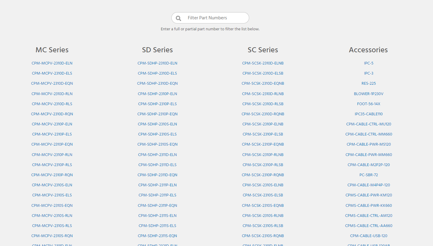
Index: All Motors/Accessories
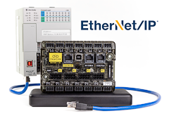
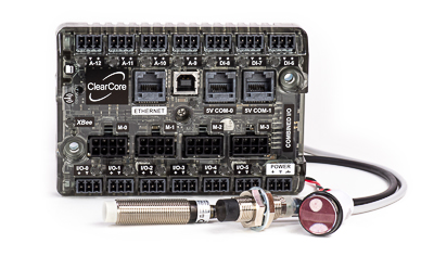
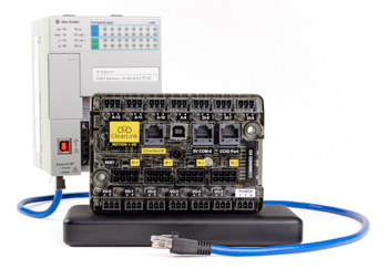
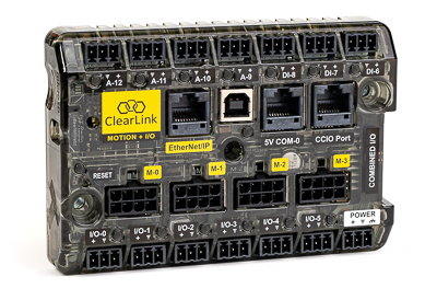
ClearCore I/O & Motion Controller
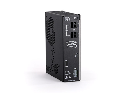
IPC DC Power Supplies
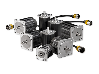
Hudson BLDC Servo Motors
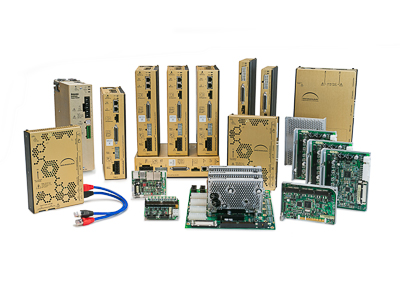
Meridian Integrated Controllers
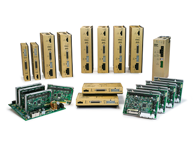
Eclipse Digital Servo Drives
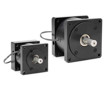
Motor Brakes
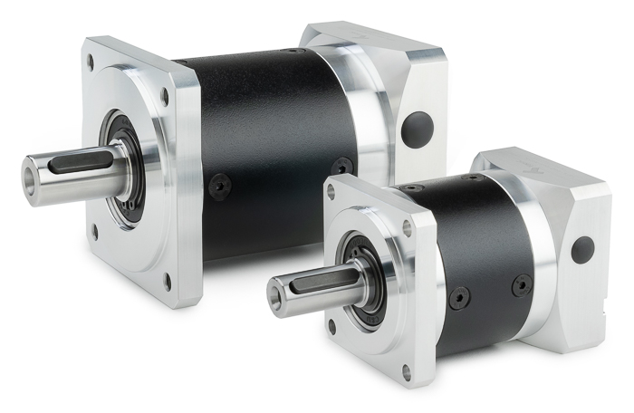
Planetary Gearboxes
Other Products
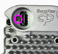
 Not Lit
 Red LED
 Yellow LED
 Yellow/Green LED
 Green LED
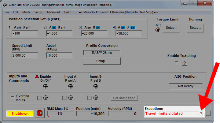
 button next to the Exceptions message to bring up hints for troubleshooting the application problem