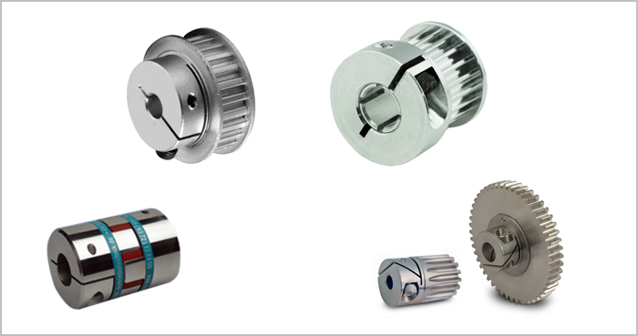
One of the most common points of failure in automated machinery is the coupling point where the motor shaft attaches to the mechanics. This is especially true in demanding motion control applications—those that include frequent start/stops, bi-directional control, frequent changes in torque direction, etc. (less common in applications that are constant velocity and one direction, such as a fan).
Most of these failures occur from selecting an improper attachment method for the type of application (although some failures occur from implementing the attachment method incorrectly). Choosing the optimal method to secure your mechanics to the motor shaft for torque transmission can help prevent failures and ensure your machine performs as expected.
Article Summary
In this article, we will:
- Review common methods for attaching mechanics to stepper motors and servo motors (the most common motors used in motion control applications). These methods include:
- Clamps or split clamps
- Adhesives
- Keyless bushings
- Keys and keyways
- Set screws or grub screws
- Pinning
- Evaluate the pros and cons of each attachment method
- Identify ideal use cases for each attachment method
- Recommend the overall best attachment methods
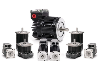
Although Teknic doesn’t manufacture mechanical stages or coupling components, we do manufacture the motion control products (brushless AC and DC servo motors) that drive these stages. Teknic’s engineers have worked on thousands of different mechanical systems over the last 30 years and are familiar with the coupling methods that work best in difficult, bi-directional servo applications. We’ve found that the ideal mechanical attachment approach for your application is not always obvious, is often different than what has been done traditionally, and will depend on a variety of metrics (including: cost, reliability and ease of use).
I: Clamps
Clamps Overview:
Clamps, also known as split clamp collars, were invented sometime around WWII as a method to address the shortcomings of using set screws (we will address set screws later on in this article). Clamps were designed for use in bombsights and guidance systems, where the main goal was to prevent axial movement. Over time, they found their way into other industries and applications, including motion control.
Clamps are commonly offered in one-piece or two-piece designs (see picture below) and they provide fairly uniform distribution of surface friction on the shaft (rather than just one point of contact like keys or set screws). The uniformly distributed force increases holding strength.
Given their ease of use, low cost, and high holding torque, Teknic recommends using split clamps in all types of servo applications. (If the motor reaches speeds above 6,000 rpm, you may want to spin-balance the component with the clamp because the construction tends to make them slightly imbalanced.)
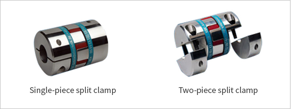
A “split hub and clamp” coupling is one where the clamp and hub are two separate components – see the picture below. In this design, the clamp is tightened around the hub which is tightened around the mechanical shaft. The hub (the pulley or pinion) has prongs that slide over the mechanical shaft and then the clamp collar slides over the pulley’s prongs. As the clamp is tightened, it compresses the prongs uniformly around the shaft.
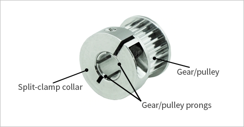
In general, two-piece clamps offer higher holding power because the full seating-torque of the screw(s) is applied directly to the clamping force on the shaft. Whereas with a single-piece clamp, some of the screw’s seating torque is needed to close the clamp around the shaft.
Although the spring force of the clamp tends to prevent the screw from backing out, you should put a little Loctite on the screw when installing it. In addition to providing extra fastening security, the lubrication of the liquid Loctite will help reduce any friction while tightening the screw and will allow you to achieve a consistent clamping force.
Pros of Clamps:
- Easy and quick to install, uninstall, and adjust
- Two-piece clamps can be assembled without removing any machine components
- Reliable
- Will not damage shaft
- Cost-effective
Cons of Clamps:
- A little more expensive than some other options
- Requires some prep prior to assembly (mating surfaces should be cleaned with isopropyl)
Conclusion:
Overall, clamps are the best option for attaching mechanics to shafts given their ease of use, effectiveness, cost, and reliability. Teknic highly recommends using clamps for any motion control application.
II: Adhesives
Adhesives Overview:
Industrial adhesives have become a popular option for attaching hardware to motors. Loctite is a brand of adhesives from Henkel Corporation that includes a number of “retaining compounds” designed to secure cylindrical components. Currently, there are about ten different types of Loctite retaining compound adhesives, all with different properties (rated temperatures, cure times, holding strengths, etc.). The most commonly used for the applications discussed in this article are the 638, 648, and 680 formulations, but you should verify the best formulation for your specific application.
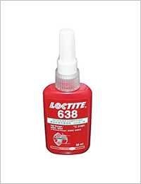
Of all the attachment options mentioned, Loctite is one of the most cost-effective solutions that takes up the least space without sacrificing reliability or holding force. One negative to using adhesives is the longer setup and removal time. That said, this approach is highly recommended – second only to clamps for any type of servo application.
Pros of adhesives:
- Cost effective (a little adhesive goes a long way)
- Allows for tightly integrated components and doesn’t require much space
- Helps fill in all micro-gaps between motor shaft and mechanics (including any surface irregularities), which helps prevent fretting and corrosion
Cons of adhesives:
- Requires time for chemicals to cure and bond
- Cure time can range from minutes to days depending on strength required (be sure to properly secure components so no movement can occur while curing)
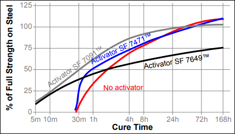
- Curing process can often be expedited by using a chemical activator, but this costs more money and may also weaken holding forces (see the example graph below for Loctite 638 cure time with and without activators)
- If bonding surfaces are not cleaned properly, the adhesive may never fully cure
- Some grades of Loctite require use of curing agent (e.g. UV light)
- Usually requires some type of heat source for removal – this process can sometimes be messy
- Presents numerous considerations for cure time, cure strength, operating temperatures, and types of materials to use with (the options of adhesive grades can seem overwhelming)
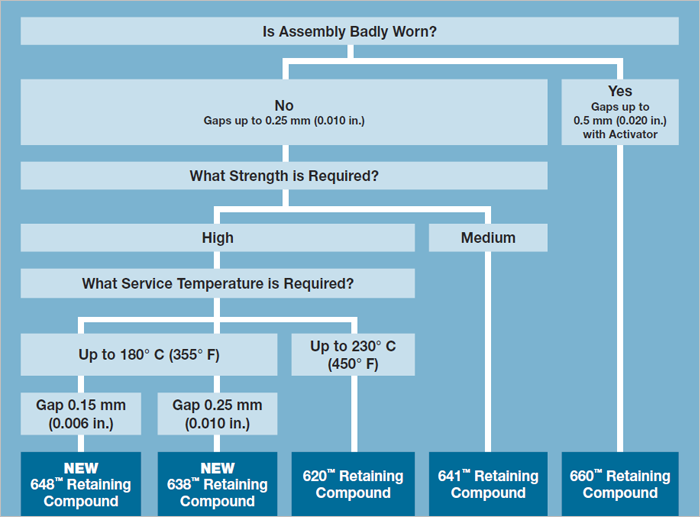
- We suggest contacting engineers at Loctite and/or using the resources available to help you choose your product (see below for an example resource). Fully understanding your application requirements, such as environmental conditions and field repair concerns, will make this process much easier
Conclusion:
Overall, industrial adhesives, such as Loctite, are one of the least expensive and reliable means for securing mechanics. When implemented correctly, Loctite can create bonds with shear strengths as high as 4,480 psi (e.g., Loctite 648 used for a steel to steel bond).
As a real world example, using Loctite 648 to secure a 3/4 inch wide aluminum timing pulley to a 5/8 inch diameter steel shaft would allow a torque of about 60 N-m of shear strength (that’s more than 8,000 oz-in). This would provide a very large safety factor when used with just about any motor with a 5/8 inch shaft.
Aside from the potentially messy and lengthy setup/removal time, there are no downsides of using adhesives like Loctite for attaching mechanics. Teknic recommends attachment with adhesive second only to clamps (especially if you need the most compact solution).
That said, for a virtually fail-safe connection, you can use a clamp in combination with a retaining compound. The clamp eliminates any worry of disturbing the adhesive while it’s curing (meaning there is no need for special fixtures), and it provides the security of a parallel attachment method.
III: Keyless Bushings
Keyless Bushing Overview:
Another common method of mechanical attachment is a keyless bushing (although they are less common than clamps). It’s a good option if you plan on attaching and removing mechanics frequently or if the concentricity of the load on the shaft is particularly important. Keyless bushings come in a variety of different brands (such as Trantorque and Fairloc) and are typically easy-to-use, self-contained devices.
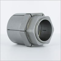
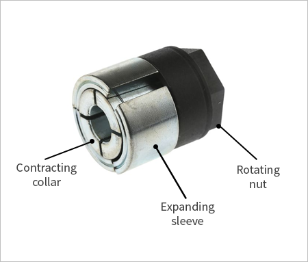
The Trantorque design (as seen in the picture above) is the most common design for shafts under 1.5 inches in diameter. A Trantorque is essentially a 3-piece bushing with an inner contracting collar, an outer expanding sleeve, and a single nut that controls both the collar and sleeve (see picture below).
As the nut is tightened, the inner collar will clamp down on the motor shaft while the outer sleeve expands (the inner collar and outer sleeve have opposing tapers, which is why one contracts as the other expands). As you tighten the nut, the outer bushing expands and the inner collar contracts – this combination generates holding forces while maintaining concentricity.
Unfortunately, keyless bushings are also one of the most expensive options and, given their size, often can’t be used to secure loads with a relatively small diameter. For example, you would not be able to secure a 1 inch pitch-diameter timing pulley to a 5/8 inch shaft (something you could do with a clamp or adhesive) because the outer diameter of the bushing itself would be at least 1 inch (i.e., the bore of the pulley would need to be about an inch in diameter). You would be forced to use a larger than optimal pulley. Keyless bushings also tend to have a large rotational moment of inertia, which can be a significant extra load when the load itself is a small diameter and thus relatively low inertia.
These two factors, along with the radial forces the bushing applies to the load, mean that the ratio of the outer diameter (OD) of the load to its bore (inner) diameter (ID) generally has to be fairly large (typically 1.5 to 2.5x).
Pros of keyless bushings:
- Evenly distributes holding forces along the motor shaft and hub (prevents slippage)
- Collar expands uniformly as nut is tightened
- Easily attaches two different sized parts (e.g. a shaft and a larger hub)
Cons of keyless bushings:
- They are the most expensive option out of all methods listed in this article (excluding the machining costs associated with pinning, discussed below)
- Some designs are complicated and require more setup time
- They have relatively large inertias
- Keyless bushings can’t be used in situations where the load components are only slightly bigger than the motor shaft (adhesives are best for low profile applications)
- They require extra prep (cleaning mating surfaces)
- The Trantorque design generally moves a small amount axially while being tightened down
Conclusion:
Teknic rarely recommends using keyless bushings because of their high price point, inertia, and large OD/ID ratio requirement. Clamps and adhesives offer similar, if not more reliable connections at a fraction of the cost. That said, if load concentricity is critical, or the hub components are much larger than the shaft diameter, keyless bushings are a good option.
IV: Key and Keyway
Key and Keyway Overview:
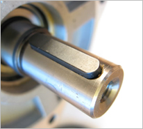
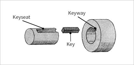
People have used shaft keys and keyways for many years. This method is still commonly used in applications ranging from HVAC fans to pumps. A key/keyway offers a fast and moderately inexpensive way of transmitting torque to the load (see Figure 8 below).
However, for bi-directional applications that start and stop often (which means the torque is bi-directional), the mechanical components will wear over time due to vibration or mechanical rubbing. Wear and fretting will eventually result in mechanical failures. While keys and keyways can work for single direction applications, they aren’t suitable for applications with frequent changes in torque direction.
Pros of key and keyways:
- One of the fastest and easiest methods of attachment
- No tools are needed because there are no set screws or bushings to tighten (although often a set screw is used in conjunction with a key to prevent axial motion)
Cons of key and keyways:
- A little bit of clearance between the shaft and key is required – this can cause backlash that will affect accuracy and cause failure over time
- If you press fit components, the shaft and components can be subjected to forces beyond spec
- The key can eventually wiggle in the keyway which will cause damage and wear
- If the key or keyway gets deformed from acceleration/deceleration or other shock loads, the system may be very hard to disassemble
Conclusion:
Given the backlash issues, high probability of wear and fretting, and eventual mechanical failure, Teknic never recommends using keys and keyways as the only form of attachment and torque transmission. In unidirectional applications that do not frequently start and stop, mechanical wear is less likely, and engineers can consider the use of a key. A key can also be used as a back-up mechanism (e.g. a clamp as the main source of torque transmission in conjunction with a key acting as a fail-safe backup).
V: Set Screws
Set Screw Overview:
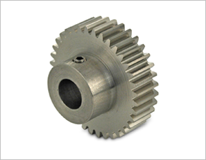
Although set screws have many drawbacks in motion control applications, they are still commonly used to secure mechanical components to a motor. In fact, the idea of a set screw (or grub screw) has been around for a long time – old enough that the first variants of set screws were made from materials like bone and wood.
Many people choose set screws because they are affordable and easy to install. However, set screws are unreliable in motion control applications and they often damage the motor shaft. While set screws may suffice in very low power applications, Teknic never recommends a set screw in any motion control application.
Pros of set screws:
- Cheap
- Widely available
- Easy to install
Cons of set screws:
- Unreliable method of attachment
- Set screw can loosen due to machine vibrations over time – allows the load to slip and move freely on the motor shaft
- If you must use a set screw, we recommend using some type of thread locking agent to prevent the screw from backing out and disengaging
- Set screws will generally gouge or deform the motor shaft. This can cause more slipping when you re-tighten the set screw to a marred shaft
- Set screws create a slight radial offset of the load and cause non-concentric motion. This hurts machine accuracy/repeatability and can result in mechanical fatigue of components over time
Conclusion:
While set screws have different characteristics that may allow for more or less holding torque (such as different screw point types – see the picture below), the risks involved and their unreliable nature make them a poor choice for demanding motion control applications.
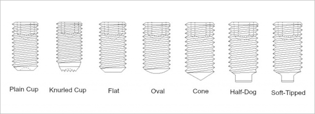
Set screws are still a potential fit for applications with tame motion demands (i.e. slow, low power, single direction, etc.) and where slipping is not detrimental to the rest of the machine. However, with so many better options available, Teknic recommends to never use set screws for any type of motion control application.
VI: Pinning
Pinning Overview:
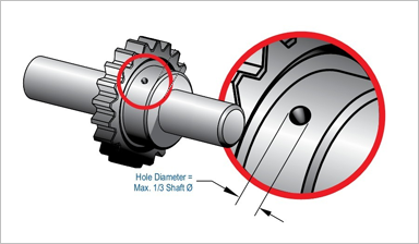
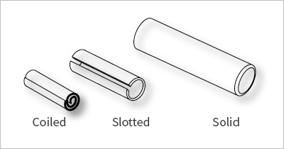
Pinning, like using set screws, is an approach that has been around for a long time and is still used today in applications ranging from firearms to machinery. While the technology and materials have changed over the years, (e.g. pointed pieces of wood are now replaced with coiled metal pins—see figure below), the concept remains the same and offers a near permanent coupling method when done correctly. However, given the machining risks and costs, this method is unreliable and expensive for motion control applications.

Pros of Pinning:
- The pins are fairly inexpensive, but the process requires proper tooling and machining technique which can be expensive
- This method can be reliable for less aggressive, unidirectional applications
Cons of Pinning:
- Challenging to do accurately and consistently – risk of machining errors and weak points due to misalignment
- Requires machining the motor shaft
- Exposes motor to coolant, machined particulate, and potential extreme radial forces
- Risk of dynamic loading and wear/fretting id the difference between pin and hole size exceeds a certain spec
- Ideally, if you must use pinning, the load and shaft should be drilled simultaneously (although this can be challenging to do)
- Different style pins (such as slotted or solid – see below) have different specs for diameter, length, material, required amount of engagement, etc.) If you must use pinning, Teknic generally would recommend a coiled pin
Conclusion:
While pinning can be successful in some applications, Teknic never recommends this method for any type of motion control system. There are readily available options that are easier to implement, less expensive, less risky, and that provide more reliable connections.
Conclusion
Given all the factors a design engineer needs to consider, along with the many different options for securing mechanics to shafts, it is easy to understand why so many engineers overlook the importance of this design step.
To summarize, set screws and keys are poor choices for reliable, automated machinery (even though there may be other types of applications where these are appropriate). Pinning and keyless bushings can work, but they have some negatives worth considering (cost, risk of machining). Split clamps and adhesives are cost-effective and reliable solutions. Teknic always recommends split clamps and adhesives for almost any motion control application.
Questions/Comments?


