


There is a wide array of actuators available and there are volumes written about every type. However, there’s not much information comparing different types of actuators in real-world settings. So, how do you choose the best type of actuator for your application? Should you use a belt or a lead screw? A rack and pinion or a ball screw? A fixed or moving motor? If you’re building your own actuator, which types are the easiest to manufacture? Which systems are the most (and least) robust?
Every day, Teknic’s servo systems power hundreds of thousands of actuators. We don’t build actuators, but, for our customers to be successful, their actuators must perform well and reliably. For the past thirty years, Teknic has worked alongside our OEM customers, helping them select and design mechanical systems to optimize their machines’ motion performance. We’ve learned quite a bit over the years and we’d like to share that knowledge with the general public.
General Comparisons Between Actuator Types
If all machines had the same motion requirements, there’d be one type of actuator—but there are many different machines with various requirements. Therefore, there are various types of actuators to achieve these requirements. So, how do you know which actuator is right for your application?
Here are the main considerations to factor in when making actuator selections:
- Price: sometimes performance requirements dictate price, but sometimes performance can be compromised to achieve price targets.
- The required velocity, acceleration, and duty cycle.
- The total moving load (including mass, moment, friction, any forces applied while moving, etc.).
- Accuracy and repeatability requirements.
- Stroke distance requirements.
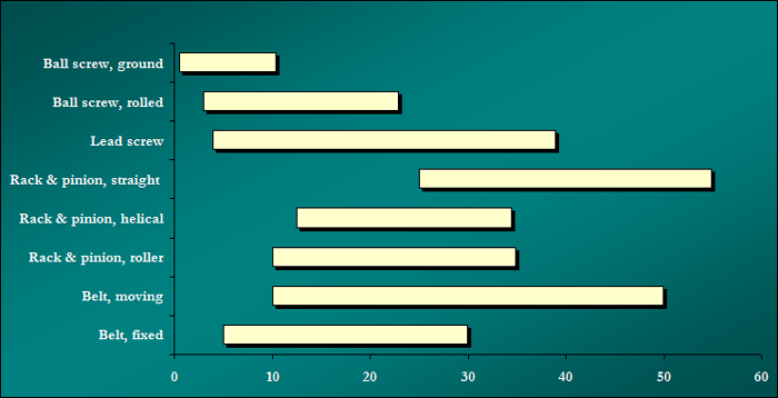
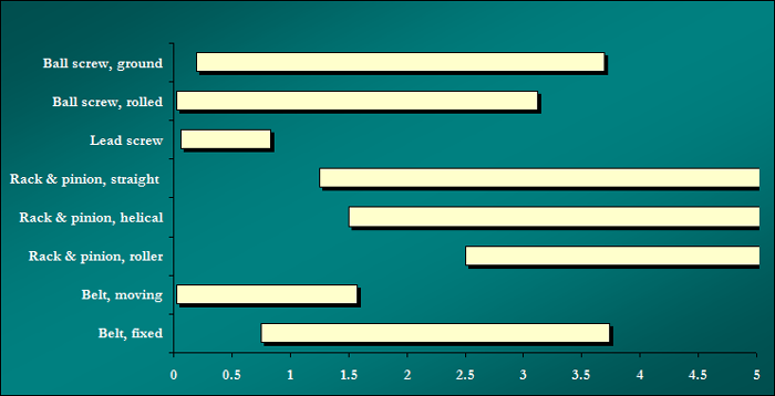
Teknic developed the graphs below to compare actuator types using the metrics above. Based on our experience, these graphs indicate where OEMs enjoy consistent success. There are actuators that fall outside of these ranges that are still successful, but these exception cases usually cost more or require unsustainable technical attention in a production environment.
For example, both a fixed belt actuator and a moving belt actuator will effectively run a light-load, short-stroke application accelerating at 0.1 g. The performance difference between these two actuators for this specific application is negligible. A fixed belt actuator is more expensive, so it doesn’t usually make sense to use one in an application like this.
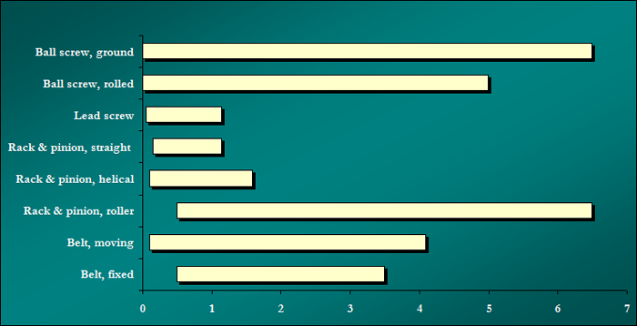
Approximate Price Range
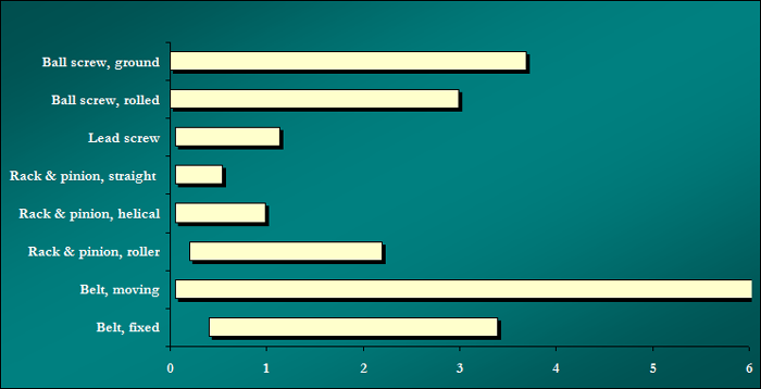
Top Velocity Range (in meters per second)
Acceleration Range (in Gs)
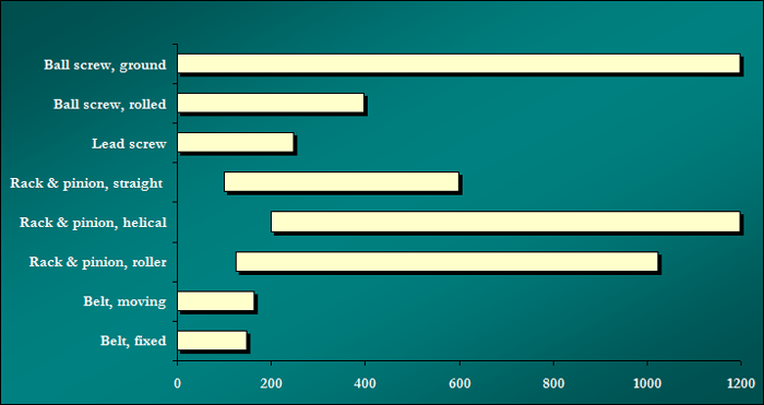
Moving Load Range (in pounds)
Position error per meter of travel (in microns)
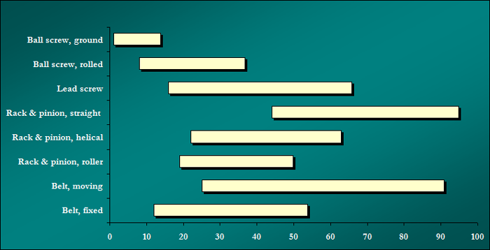
Repeatability per meter of travel (in microns)
Actuator travel distance (in meters)
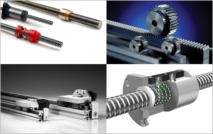
Specific Drive Systems: Use cases, pros and cons, selection considerations, tips and tricks
Ball Screws  [1]
[1]
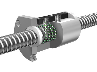
Application Usage Overview:
Out of all the actuators highlighted in this article, ball screws can drive the widest range of applications. They work well with both heavy and light loads, run precisely at high and low speeds, and have excellent repeatability and accuracy. Ball screws provide consistent machine-to-machine performance with minimal assembly effort. Even the selection process for ball screws is pretty straightforward.
On the other hand, these benefits come at a cost: money (sometimes a lot of money).
Ball screw Pros and Cons:
| Pros | Cons |
|
Selection considerations:
1. Higher cost does not necessarily mean better performance or value.
- Ball screws are a prime example. There are quality US and German suppliers offering equivalent product at half the cost of popular brand names. Shop around carefully.
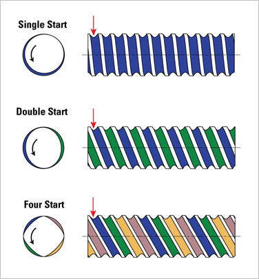
2. The number of starts has an effect on load capacity, price, audible noise, and more.
- For a given lead, increasing the number of starts [5] can sometimes improve overall ball screw specs, such as load capacity. People often think that having more starts has no downside. However, multiple-start ball screws are more expensive, louder, and introduce more opportunities for failure than single-start units.
3. It’s important to understand sealing requirements.
- Unnecessary sealing (of the nut, bearings, etc.) adds significant friction, which means you have to use more powerful (and costly) motors. On the flip side, units that are not properly sealed for the operating environment fail quickly.
4. Rolled vs. ground screws.
- Rolled screws are less expensive but historically less accurate than precision ground screws. However, recent process advancements have improved rolled screw accuracy while maintaining a cost advantage over ground screws. As a result, rolled screws are often a compelling value for many applications.
Tips and Tricks using ball screws:
1. Are you using a gearbox or belt stage between the motor and screw? If yes, consider one of two things:
- Use a higher gear reduction with a faster screw lead (keeping the overall linear distance traveled per motor revolution the same). You’ll experience a number of benefits by shifting the effective “gearing” from the screw to your gearbox or belt stage. With the combination of higher input gear ratio and a longer lead, the system will still maintain the same linear force, but this setup will reduce the reflected inertia, audible noise, and chance of screw whip.
- If possible, switch to direct-driving the screw. Direct-driving often increases accuracy and reduces backlash, and simultaneously lowers system cost—a larger servo is often less money than the combination of reduction stage and a smaller motor.
2. The coupling between the motor and the screw is critical (but is commonly not given much thought).
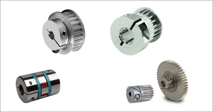
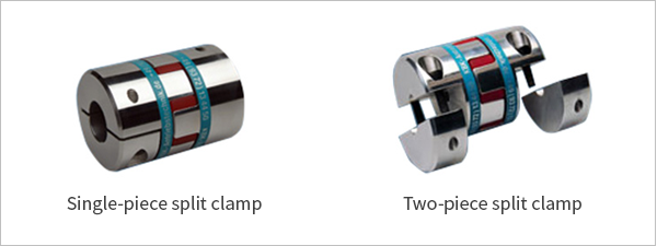
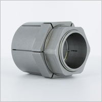
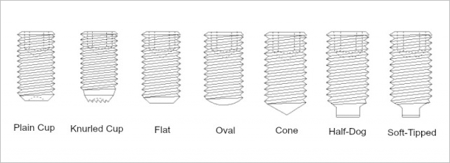
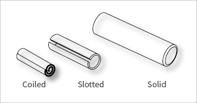
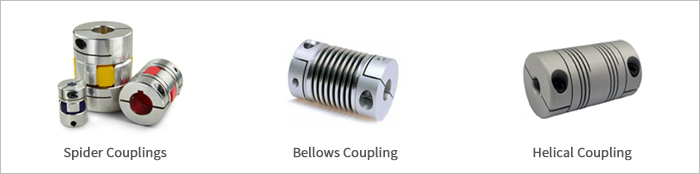
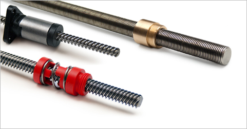
- Teknic recommends jaw-style (“spider”) couplings with a 92 or 98 durometer Shore A spider (see picture below). For reasons beyond the scope of this article, Teknic recommends against Shore D spiders and metallic spiders. Additionally, be sure to use a coupling that uses a clamp-style shaft attachment method, not a set screw.
- Bellows couplings will work well, but they are more costly and have tighter alignment requirements than jaw-style couplings. If the machine mechanics (motor and screw) have different shaft diameters, the bellows coupling may need to be custom. Jaw couplings come in three separate pieces, so they can be purchased with different bore sizes and easily mixed and matched to suit.
- Helical couplings have low torsional stiffness that limits total system bandwidth and can cause extra mechanical resonance. Helical couplings are sometimes acceptable in applications using stepper motors, because the spring compliance can smooth out stepper cogging. However, for applications using high-performance servos, helical couplings limit performance and you should avoid using them.
- Don’t use a solid coupling. Solid couplings require nearly perfect shaft alignment, which is not reasonable when building multiple machines. Many times, using a solid coupling results in long term damage to the motor and screw bearing systems.
Summary:
Out of all the mechanical drive systems we cover in this article, ball screws have the broadest range of capability. Moreover, ball screws are typically the most successful option for OEMs who want to design their own actuators.
Lead Screws[6]
Application Usage Overview:
It is not necessarily easy to properly select lead screws, but when specified correctly, lead screws provide good accuracy and repeatability for the money. In addition, well-designed lead screw systems are durable and offer repeatable results in high-volume manufacturing environments.
Lead screw Pros and Cons:
| Pros | Cons |
|
|
Selection considerations:
1. Screws with short leads ![]() [7] are inefficient.
[7] are inefficient.
- As you increase the “gearing” of a lead screw (i.e. decrease the linear distance traveled per revolution of the screw), you simultaneously decrease the screw’s efficiency. We commonly see customers select leads that are too fine (too many revolutions per linear distance traveled), where the gain in mechanical leverage ends up as a net loss of force due to loss of efficiency.
2. Select materials with care.
- Lead screws have a nut that slides along the screw surface. Choosing the optimal combination of nut and screw material is critical because of friction. For example, a brass nut on a steel screw has a dry (unlubricated) coefficient of friction (μ) of 0.41, whereas a polyacetal nut on a Teflon-coated screw has a dry μ of .08. This change of material results in a 220% change in efficiency on a 15mm diameter, 10mm lead screw. Friction is just one of many material considerations (others include ambient temperature, environmental conditions, duty cycle, etc.)
3. Stay within your “PV” limits when using polymer nuts.
- Polymer nuts have a continuous duty rating (which is below the peak rating) called the Pressure Velocity rating (or PV for short). Pressure between the screw and nut (which equals the driving force divided by the contact area between the screw and nut), along with sufficient relative surface speed will generate heat. A high enough heat will deform and permanently destroy the polymer nut. You should also consider the duty cycle of motion. Often, the screw can run at relatively high speed and/or pressure as long as it’s for brief periods of time (so that the nut can sufficiently cool between subsequent moves). All lead screw manufacturers readily provide this information so that you can choose the appropriate screw for your application.
4. Select the correct number of starts.
- A fast lead (large linear distance of travel per revolution of the screw) has “dead” space between threads—space that can be used for additional, independent threads. These independent threads (referred to as “starts”) increase the force capacity for a given lead, but also increase friction (thus heat) and impact the PV rating. Lead screw manufacturers will assist with this selection, but don’t assume that additional starts are always better.
Tips and Tricks using lead screws:
1. When speed and acceleration are important, use “fast” leads with enough starts to support the required forces.
- Teknic acquired two off-the-shelf lead screw actuators with identical specs, except for one difference: one actuator uses a single start (1-start), 5 mm lead screw and the other uses a 4-start, 20 mm lead screw. The 5 mm lead actuator accelerates our payload at 0.5 G to 333 mm/sec maximum velocity. The 20 mm lead actuator, using the same motor and amount of electrical power, accelerates the same payload at 1.7 G to 1,333 mm/sec velocity. So, just a thread change enabled a 340% increase in acceleration and a 400% faster linear velocity.
2. Gear more in the reduction stage and less in the screw.
- If you have a reduction stage between the motor and the screw, increase the reduction ratio and proportionately select a longer (faster) lead. For example, if you have a 2:1 ratio into a 5 mm lead, change to a 4:1 ratio and a 10 mm lead. This change improves system efficiency (from 15% to 50% depending on friction coefficients) and decreases mechanical wear, audible noise, and reflected inertia.
3. The coupling between the motor and the screw is critical (but is commonly not given much thought).
- Teknic recommends jaw-style (“spider”) couplings with a 92 or 98 durometer Shore A spider (see picture below). For reasons beyond the scope of this article, Teknic recommends against Shore D spiders and metallic spiders. Additionally, be sure to use a coupling that uses a clamp-style shaft attachment method, not a set screw.
- Bellows couplings will work well, but they are more costly and have tighter alignment requirements than jaw-style couplings. If the machine mechanics (motor and screw) have different shaft diameters, the bellows coupling may need to be custom. Jaw couplings come in three separate pieces, so they can be purchased with different bore sizes and easily mixed and matched to suit.
- Helical couplings have low torsional stiffness that limits total system bandwidth and can cause extra mechanical resonance. Helical couplings are sometimes acceptable in applications using stepper motors, because the spring compliance can smooth out stepper cogging. However, for applications using high-performance servos, helical couplings limit performance and you should avoid using them.
- Don’t use a solid coupling. Solid couplings require nearly perfect shaft alignment, which is not reasonable when building multiple machines. Many times, using a solid coupling results in long term damage to the motor and screw bearing systems.
4. Certain types of nuts can reduce backlash and improve repeatability.
- If you have a horizontal application where accuracy and repeatability are important, use anti-backlash nuts. While the specifics are beyond the scope of this article, anti-backlash nuts have a force-applying element (which can be rings, springs, axially-compressed fingers, etc.) that removes clearance between a multi-part nut and the screw. Anti-backlash nuts are application specific, so be sure to contact a lead screw manufacturer for assistance with selecting the appropriate nut.
5. In some circumstances, lead screws can eliminate power-off brakes.
- Lead screws have different efficiency for forward driving (a motor driving the screw and moving the load linearly) and back-driving (a linearly moving load back-spinning the screw—i.e., the load is spinning the motor). A good example of back-driving is gravity acting on a vertical load.The right combination of screw lead and coefficient of friction will lock the nut in place when the load is pushing back against the screw. No amount of force will cause these screws to back-drive because the linear force produces a larger component vector of friction force than the component vector that creates rotation. Some people implement power-off brakes to prevent vertical loads from falling when motor power is off, but brakes add more cost and complexity. On the other hand, many people carefully choose screws with specific parameters that do not allow back-driving (but still meet forward motion requirements). These screws result in lower cost and simpler design. One thing to note is that screws with zero back-driving efficiency are not very forward efficient either, so you have to review all factors.
Summary:
There is a learning curve involved with proper lead screws specification, but lead screws can offer compelling advantages over competing mechanics when specified well for the application (i.e. affordability, precision, range of options, reduced maintenance, etc.). Moreover, lead screws enable easy-to-achieve machine to machine repeatability compared to other low cost mechanical drive technology.
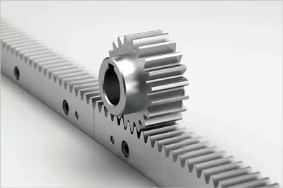
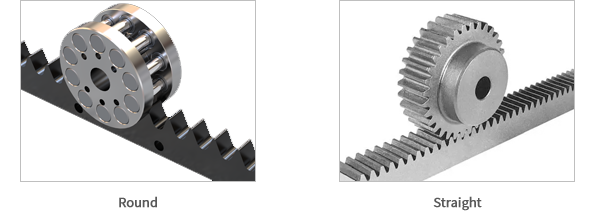
Rack and Pinions
Application Usage Overview:
Rack and pinions are common among applications with heavy loads and long strokes because of their load capacity and price. However, system performance and price vary due to differences in geometric properties and there are significant quality differences from manufacturer to manufacturer.
Rack and pinions offer some unique advantages over other linear motion technologies. For example, you can drive multiple pinions (thus multiple independent axes) per rack, or the motor can drive the rack (rather than the pinion), creating a “rack rod” (a rod that pushes like a pneumatic piston) to provide accurate thrust in a small footprint. (As a note, you can accomplish both of these examples with screws by spinning the nut instead of the screw, but that is usually more difficult.)
Standard (straight gear cut) rack and pinion Pros and Cons:
| Pros | Cons |
|
|
Selection considerations:
1. Performance remains consistent even as actuator length changes.
- Motion performance and motor requirements remain consistent as actuator stroke changes. Other actuators have characteristics (compliance, reflected inertia, resonance, etc.) that suffer as total stroke increases. As a result, rack and pinions are a popular choice for OEMs producing large equipment or equipment of various sizes.
2. Costs scale nicely.
- The cost for the “first inch of travel” is more expensive for “moving motor” mechanical designs (e.g. rack and pinions) than for “stationary motor” designs. “Moving motor” actuators have the additional burden of the entire motor assembly, e-chain management, flex cabling, etc. However, the cost of adding additional travel to a rack and pinion system is among the lowest of any actuator technology. As a result, if your application requires more than two meters of travel, rack and pinions are often the best value.
3. A rack and pinion is not a good choice for certain environments, such as labs or clean rooms.
- It’s important to understand the type of environment where you (or your customers) will run the application. A rack and pinion system is not the quietest actuator and the audible pitch can be unpleasant. Additionally, the lubrication on the system isn’t sealed, so the mechanics are not particularly clean.
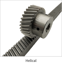
4. You can mitigate some of the cons—for a price.
- Helical teeth. Helical cut teeth (both on the pinion and rack) engage at an angle, which smoothes motion and reduces backlash. The downside is reduced efficiency because forward thrust is maximized at a 90 degree tooth angle (i.e. a straight-cut pinion). In addition, helical pinions want to follow the tooth angle (thus drive off the rack), so you need to include proper bearing structures to keep the pinions on the racks. Both factors (efficiency loss and bearing structure upgrades) increase installed costs by $100-$200 an axis, but helical teeth are worthwhile in applications requiring higher accuracy, lower backlash, and/or smoother motion.
- Roller rack systems. These systems use pinions comprised of bearing-supported rollers instead of toothed gears. The rollers smooth motion, provide pre-loading (to reduce backlash), run up to 10 meters per second, and are audibly quieter than conventional racks. The downside is that roller racks have limited pinion diameter options and cost much more (up to $1000 more than helical designs). It’s reasonable to compare roller racks to ball screws (given their performance and price) even though the design is a rack and pinion. That said, even compared to ball screws, roller racks are more expensive until the stroke is between two and four meters in length. (The exact stroke length where the prices begin to converge depends on roller pinion and ball screw grades.)
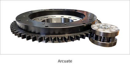
Given these factors, roller racks are only competitive in long stroke, high precision applications – with one exception. The exception is rotary applications. Arcuate roller racks can be cost competitive and offer exceptional stiffness when compared to strain wave reducers (starting in moderate platen diameter sizes, ~250 mm+).
Tips and Tricks using rack and pinions:
1. Pinion pitch diameter has a great deal of impact on the design (beyond just leverage).
- Comparing two pinions of different diameter, but otherwise the same design, a smaller diameter pinion has greater mechanical leverage. Additionally, the gearbox’s backlash translates to less linear distance. The smaller pinion provides more force and superior accuracy compared to the larger diameter pinion. On the other hand, the larger diameter pinion has more teeth engaged, which reduces vibration and decreases wear. An effective compromise is often a smaller pinion with a finer tooth pitch (generally try to target 5 or more teeth engaged). This allows the advantages of smaller pinions, while also mitigating wear and vibration.
2. Routine maintenance is essential.
- Properly maintained, rack and pinions are good for hundreds of millions of pinion revolutions. Yet, many customers fail to maintain these mechanics (despite simple procedures) and the components degrade after even just a few months. You should consider investing in self-lubricating systems if you do not expect to be able to keep up with the ideal level of maintenance.
3. Use a matched rack and pinion from an actuator company.
- Teknic used a laser interferometer to measure total pitch error between the first and last tooth on two different 2-meter stroke systems. One rack was hobbed by a machine shop; the other by Atlanta Drives. Both units had identical specs on paper. The generic rack had 15 mils of accumulated error, while the brand-name was under 2 mils. The superior rack cost only $46 more (as of 6/2018)—certainly a worthwhile investment.
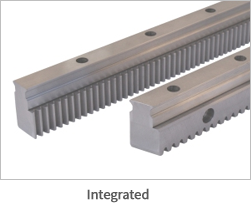
4. Consider an integrated rack (a.k.a. rack & rail).
- Integrated rack and bearing rail designs typically cost more than the separate parts, but many OEMs find this to be the best value. Integrating the rack and rail saves space, reduces manufacturing time, and eliminates alignment issues as well as the need to machine separate mounting surfaces.
Summary:
Rack and pinions offer flexibility and significant load capacity and are common in heavy, longer stroke applications. They are especially prevalent at OEMs that make large equipment with various stroke configurations. For high-precision applications in the 2 meter or longer range, it is worth considering helical racks and perhaps even roller racks versus conventional straight (spur cut) racks.
Moving Timing Belts
Application Usage Overview:
Timing belts are cost-effective, audibly quiet, repeatable, and can accelerate light loads at remarkable rates. Belts have been around for decades, so individual parts are available from many sources, but this creates a two-fold problem. First, when buying parts from various sources, you need to be an expert on combining those components. Second, the quality of “universal” parts varies from manufacturer to manufacturer. So, proper selection and sourcing are equal challenges. That said, belt systems are cost-effective, reliable actuators for applications with moderate load weights and reasonable accuracy expectations.
Moving belts Pros and Cons:
| Pros | Cons |
|
|
Selection considerations:
Belt systems can be low cost and effective. However, there are more challenges and pitfalls associated with designing belt actuators than other types of actuators. A turn-key belt actuator removes most of the challenges and we strongly recommend this route, but if you’re making your own belt actuator, here are factors to consider:
1. Moving belt actuators are particularly sensitive to change in three areas:
- Belt Width:Timing belts are rated for capacity and not system dynamics. The most narrow belt rated to meet your acceleration spec, carry your specified load weight, and withstand your application’s duty cycle is likely too compliant (stretchy) for quality motion performance. So, apply the “1-2-3 rule-of-width” (more information on this in the “tips and tricks” section for belts).
- Load Inertia:Many people remember to consider mass, but forget about (or ignore) the load inertia reflected to the motor.Ignoring reflected inertia is unwise in any motion system. So why bring it up here specifically? Belts have high back-driving efficiency and low effective gearing [8], so if you push the load by hand, it has a uniquely light finger-tip feel. This combination lulls too many engineers into ignoring the effect of reflected inertial mismatch.
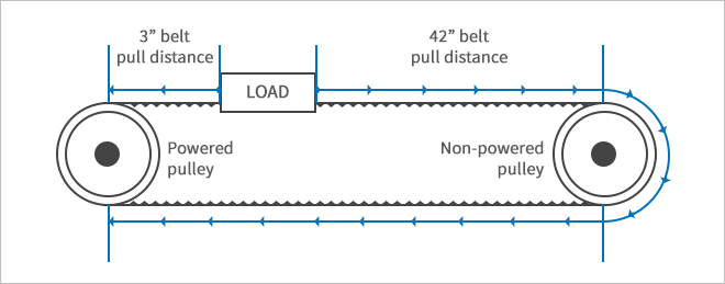
- Stroke Length:Actuator performance can vary as stroke length changes. Belt actuators, in particular, are so uniquely sensitive to changes in stroke that they often require different configurations for every stroke length.A belt can only pull a load, it can’t push one. So, an accelerating or decelerating load experiences force from the opposite side. This also means that the length of the “pulling” belt changes depending on where the load is within the stroke of the axis. Moreover, for every unit of increased stroke length, the change in belt length is double that distance. As a result, even moderate changes in actuator stroke may necessitate changes to pitch, width, tooth profile, and electrical power to maintain consistent motion performance.
2. Operating environment affects performance.
- The optimal belt material depends on application temperature, potential contaminants, static discharge ratings, etc. For example, common bearing grease decreases the life expectancy of some non-urethane belts by as much as 75%. You’ll want to check with the belt manufacturer and explain the specifics of your operating environment prior to selecting the belt material.
3. You need to run and then re-tension belt actuators before you put the axis into service.
- Most belt actuators have a break-in period during which the belt system loses tension, but after this period tension stays consistent. To prevent issues, exercise the actuator through the break-in period and then re-tension the belt prior to actual use (the reasons for tension loss in the first few hours of use are beyond the scope of this article, but suffice it to say almost no belt system is immune to this).
4. Proper tensioning is the key to longevity and performance.
- Too much tension reduces belt life, bearing life, and smoothness. Too little tension degrades repeatability, decreases belt life [9], and leads to position loss due to ratcheting [10]. Even when you’re within and acceptable tension range, consistent tension from actuator to actuator is the key to repeatable performance.
Tips and Tricks to using moving belts:
1. Apply the “1-2-3” rule of belt width.
- Identify the manufacturer’s recommended minimum belt width based on your load, torque demands, and duty cycle. While that minimum width won’t catastrophically fail, it’s likely too compliant for ideal dynamic motion control. To get good performance, select a belt twice that width, but don’t triple the width because excessive width brings other downsides (such as greater bearing structure requirements, higher motor torque demands, and loss of smoothness).
2. High reflected inertia is problematic with belt systems. Don’t ignore it.
- It’s generally accepted that the reflected load to motor inertia ratio should be no greater than 10:1. Teknic’s servo systems have features that allow a greater (sometimes much greater) ratio when the load and motor are tightly coupled.The acceptable ratio of load inertia to motor inertia depends on a lot factors, but the type of actuator is one of them. The challenges with belts are: 1) low mechanical leverage increases reflected inertia, 2) acceleration induces stretch/deflection in the belt and 3) load to motor coupling stiffness varies based on the direction the force is being applied. So, for a given load weight, moving belts often have higher reflected inertia and more dynamic variability than other mechanical drive systems.
3. Use aluminum pulleys.
- Steel pulleys have almost triple the inertia of equivalently-sized aluminum pulleys. When your payload is light (which is where belts are often the optimal choice), accelerating steel pulleys can require as much or more torque than accelerating the load itself.
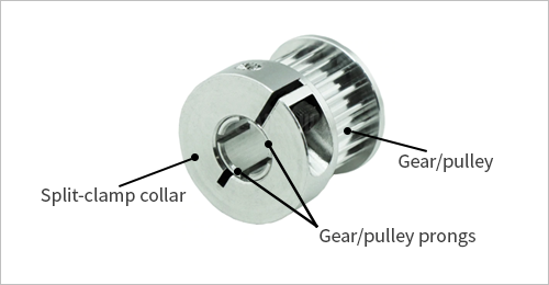
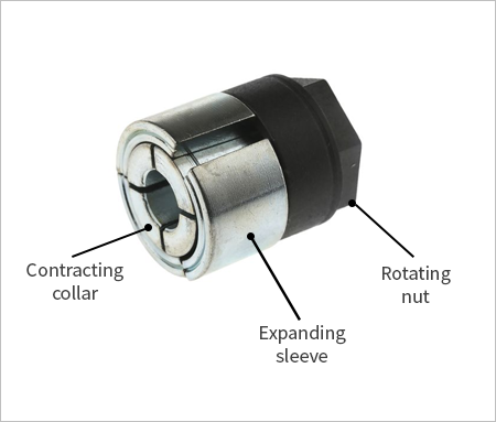
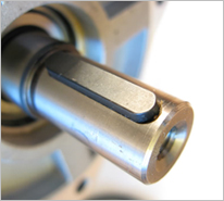
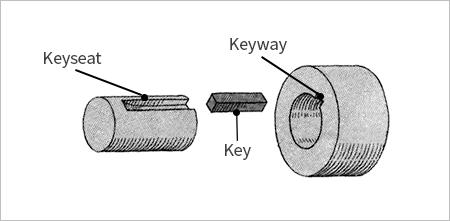
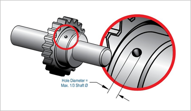
4. Bond or positively lock the pulley to the motor shaft.
- The point at which the motor shaft attaches to the pulley is a common field failure with belt drives. Never use a set screw or key by itself. Use clamp-style units, locking hubs, or adhesive (e.g., Loctite retaining adhesive). For details on making a high-performance bond, read this article.
5. Select the tooth profile with care.
- Tooth shape impacts smoothness, repeatability, accuracy, and force capacity. The bullet points below are true for most servo applications:
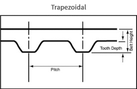
- Trapezoidal-shaped teeth can transmit significant force and offer low backlash, but trapezoidal-shaped are louder than other tooth shapes and can cause uneven, or “clicky” motion. Moreover, trap-shape teeth wear quickly in high torque/ high speed applications due to stress concentration at the belt-pulley interface.
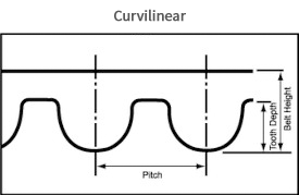
- Curvilinear teeth (a.k.a. modified round, HTD, or “Gates” belts) are smooth-running teeth developed to 1) alleviate stress concentrations found in trap profiles and 2) improve power handling capacity. The trade-off, however, is that first-generation curvilinear designs have more backlash.
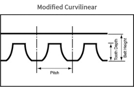
- Modified curvilinear teeth have shallow depth, greater flank angle than other belt designs, and the load is distributed among the engaged teeth and the base between the teeth. This results in high force transmission capability, smooth rotation, and almost no ratcheting. Unfortunately, modified curvilinear belts have limited material options.
6. Consider tooth pitch and width trade-offs.
- Increasing tooth pitch (leaving all else the same) may increase force capacity a small amount, but decreases accuracy significantly. Usually, a slightly wider belt with a finer tooth is best for positioning applications. Regardless of pitch, continue to apply the 1-2-3 rule of belt width selection.
7. Buy a matching pulley for your belt, not just a compatible one.
- Belts work with pulleys that have matching tooth profiles, but the performance greatly improves when you use a pulley specifically designed for that belt. For example, an HTD pulley will work with a GT-2 belt (it has the same nominal tooth profile), but the pair will be less smooth and less accurate than the GT-2 belt with a matching GT-2 pulley.
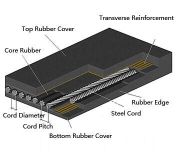
8. Select belt materials![]() [11] carefully.
[11] carefully.
- Belts that look nearly identical offer different stiffness, accuracy, and longevity based on what’s under the surface (cord type, weave, reinforcement material, etc.).
Summary:
Belts have more elements to specify—especially pertaining to their construction—than any other mechanical drive technology. If you invest the time in learning about your options and couple that with carefully-considered motion goals and quality assembly practices, belts can be high-value actuators.
Fixed belts
Application Usage Overview:
Fixed belts are similar to rack and pinions. The belt pulley moves down the fixed belt much like a pinion moves down a fixed rack. A well-designed fixed belt provides better repeatability and fewer tensioning challenges than moving belts. Additionally, a fixed belt is more quiet and accurate than most racks. However, the load capacity and environmental range for most fixed-belt actuators is limited compared to rack systems.
Fixed belts Pros and Cons:
| Pros | Cons |
|
|
Selection considerations:
1. The use cases are limited.
- Fixed belt actuators are typically a good design choice in a subset of applications that include most or all of these characteristics:
- Long stroke (2+ meters)
- Light loads (under 25 pounds or so)
- Moderate to high speeds (1+ meters per second)
- Low noise requirement
2. Go off-the-shelf if you need more range of capability.
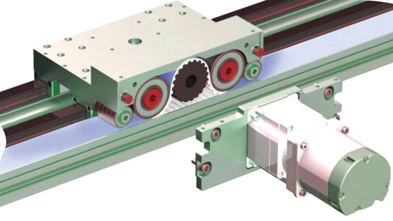
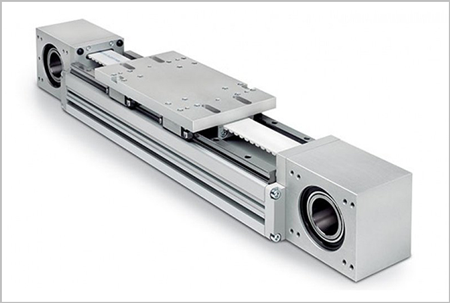
- If your application does not meet all four parameters mentioned above, other actuators are typically a better fit. However, there are off-the-shelf exceptions. One is the ServoBelt™ Linear
Drive[12], whose design improves load capacity and accuracy and allows for multiple carriages per axis.
3. There is less universal support than for other actuators.
- Fixed belt systems are not common, so you won’t find a large community of users for support.
Tips and Tricks using fixed belts:
1. Both sides of the belt matter.
- Like all belt drives, tooth selection is critical. In addition, fixed belts use idler rollers on the back of the belt, so this design is also sensitive to surface materials on the back of the belt. Be sure to select a belt with a backer that is rated for idler rotation.
2. Lock idlers in position.
- Calibrated spring idlers effectively tension and wrap the belt, but you must lock the idler in position prior to motion. Springs will compress during acceleration, leading to momentary position loss and even permanent position loss if teeth jump. In addition, the compliance of the springs will introduce dynamic issues into the system.
3. Clamp the ends properly.
- The idlers in a fixed-belt design ensure plenty of teeth in mesh with the drive pulley. However, tooth engagement in the end clamps is often overlooked. The teeth in the end clamps flex during acceleration, so be sure to engage at least 6 teeth at both end clamps.
4. The motor is driving much more than just the payload.
- Moving motor designs are impacted by motor weight, the effective load of the e-chain (which is position-dependent), the ratcheting effect of an e-chain, the force of flexing cable, etc. This adds extra weight as well as position and velocity-dependent variable drag.There are other actuators that experience this issue, specifically rack and pinions, but if you have a rack system designed for a 1,000 pound load, these effects are usually insignificant. Moving belts, on the other hand, are often built for light loads using no gear reduction, and a small motor. As a result, a motor sized only for the payload won’t have the power (or gearing) to mask dynamic issues brought about by these extra components. So keep space for a motor that’s larger than payload calculations indicate.
Summary:
Fixed belts are effective actuators—when applied properly. OEMs that use these actuators in light-load, long-stroke applications with a motor sized to control all the forces (not just the payload) are generally successful. The unsuccessful companies either 1) undersize the motor with no room for a larger motor, or 2) tweak the system until they get the desired performance, but it’s unrepeatable in a volume manufacturing environment. If you have realistic performance expectations and a motor sized to handle all the forces, fixed belts can be the basis of highly-effective motion axes.
Advice applying to all actuator types
Over the last three decades, Teknic has learned a few things that apply to all types of actuators:
1. Actuators—and their parts—are not commodities.
- Components sharing similar paper specifications often yield vastly different real-world results. Actuators and mechanical drive parts are not freely interchangeable. So test the exact device you intend to use, on the frame you intend to use, and in the environment where you intend to use it.
2. Have realistic expectations.
- It is challenging to achieve significantly better performance than normal for a given type of actuator—you will most likely run into a lack of manufacturability or ongoing maintenance hassles [13]. Even if you’ve tweaked a single actuator to perform uniquely well for its class, tolerance stack-up and mechanical wear over time will make your machine-to-machine performance (and individual machine performance over time) much lower than your finely-tuned prototype.
3. Making your own actuator is not cheap or easy.
- OEMs often make their own actuators, but it’s not a simple endeavor. If you design your own actuator, 1) you will take longer to get the product to market, 2) you’ll invest more time developing an actuator and less time perfecting machine processes, and 3) your real costs are almost always higher than first estimated (and you won’t always save money compared to off-the-shelf solutions). So, unless you’re manufacturing at least hundreds of machines annually, or you have unique constraints, we strongly recommend that you consider integrating an off-the-shelf actuator.
4. Inexpensive individual drive components don’t necessarily mean inexpensive actuators.
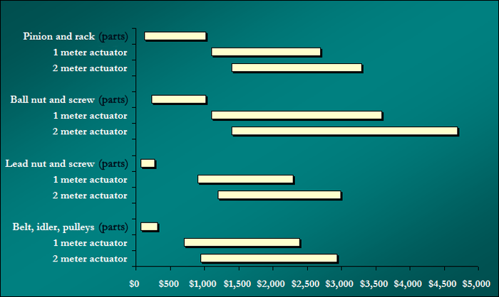
- Individual parts that are less expensive up front may require more costly and extensive manufacturing processes, so the total cost overall may add up to more than you expect. For example, you can purchase a belt and pulley for under $100, but a ball screw and nut (of the same length of travel) might cost $500. However, belt actuators often require additional machining, more manufacturing steps, and a break-in period. This increases costs of turn-key belt actuators so an off-the-shelf ball screw actuator is sometimes less money than an off-the-shelf belt-driven actuator [14]. It’s important to focus more on your application requirements rather than the cost of subcomponents. Here is a graph comparing the price of the individual parts to the price of the finished actuator (prices are much higher for some specialty actuators, but we removed them to show the typical price range).
5. Don’t spend extra money for precision components, unless you’re willing to make the entire machine precise.
- Often the weakest link related to a machine’s accuracy is not the mechanical drive. Issues such as thermal expansion (and contraction), machining imperfections, frame flex and vibration, motor accuracy, etc. can have significant effects on overall accuracy. Unless you pay careful attention to all the factors that affect accuracy, the extra precision of expensive components may be wasted. For example, we often see the use of precision ground ball screws where much cheaper rolled ball screws would not significantly affect the overall machine accuracy.
6. Be sure to consider the reflected load inertia to the motor.
- We see some motor models adeptly control thousands of pounds in some applications, yet the very same motor models fail to adequately control a mere 5 pound load in other applications. The difference between success and failure in these applications is the motor’s leverage on the load.The best indicator of leverage is calculating the reflected load inertia back to the motor. Teknic has seen hundreds of painful redesigns and dozens of outright total machine failures due to engineers overlooking this relatively simple calculation at the start of the specification process.
Selecting the best actuator for your application—Our Summary.
Now that we’ve highlighted various actuators, how do you go about making a selection? These are our suggestions:
1. Many factors influence which actuator makes the most sense for you. You’ll want to consider these factors in light of your application and create an inventory of answers to select the most appropriate actuator.
- Quantify your entire moving load weight. Be sure to include all the moving parts in the actuator (don’t forget the e-chain!).
- Carefully consider your quantitative motion goals, such as accuracy, repeatability, move time, etc.
- List your qualitative goals (such as audible noise) and prioritize them.
- Consider the machine’s working environment. Is it dirty or clean? A quiet laboratory or a noisy factory floor?
- How much maintenance (or abuse) do you expect from machine operators?
- Carefully consider your manufacturing capabilities. Is your manufacturing team made up of old-world craftsmen, or laborers who follow basic work instructions, or something in between? The skill sets required to build different types of actuators vary. Make sure there’s a good match between the manufacturing requirements of your actuator and your manufacturing team’s skill set.
2. Now that you have your inventory of needs and capabilities, use the information in this article to consider different actuators. There is a good chance one actuator stands out.
- If at this point, there are still multiple options, you have a pretty flexible application. In this case, go with the actuator that is the easiest to implement in your machine.
3. With your actuator selected and requirements quantified:
- If you’re a high-volume OEM machine builder, design your own actuator using a holistic system-wide approach. Consider starting with an off-the-shelf actuator of a similar design so that other disciplines in the design team (such as software) don’t get stuck waiting for your mechanics to be ready.
- If you manufacture products using automated machinery—even if you use many axes of motion—don’t make your own actuators. Narrow your selections to a few off-the-shelf options and test them to arrive at a final selection. Most manufacturing companies are best served by focusing on making their products and processes better, not coming up the learning curve that actuator companies already understand.
- If you’re in the market for a few actuators, buy the best one the budget will allow, oversize the motor a bit to be safe, and forget the extensive research. Time is money.
One final point. Your application is a system. Take a balanced approach. A system is only as good as its weakest link. Even the world’s best motors can only do so much with poor mechanics—or even good mechanics that are misapplied. Carefully quantify your requirements and take a holistic approach.